

How can a grid act as a reflector? Doesn’t make much sense when you think of it, but when we are talking about electromagnetic radiation, they definitely can. Probably the most common example you see is in satellite TV offset reflector antennas, but you also see it in radio telescopes. The dish is not made from a solid structure, it’s a mesh or has holes in it, and yet it can easily reflect the electromagnetic radiation to the receiver at the focal point of the parabaloid. There are other structures that you can make that are not solid metal, but act as a radio frequency mirror.

A polarisation selection grid is a set of parallel metal grid lines which allow the transmission or the reflection of radio frequency radiation depending on the polarisation of the radiation. This allows a single structure to act either as a mirror for radio frequency radiation or as something that does not exist. When the polarisation of the electric field is parallel to the grid lines the electric field induces a current in the grid lines which reflects the signal and the grid is seen as a radio frequency mirror. When the polarisation of the electric field is perpendicular to the grid line no current is induced and the electromagnetic radiation passes through the grid.
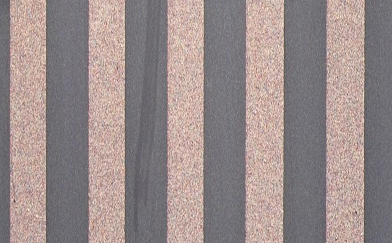
Polarisation selection grids are often manufactured with metal wire tracks, usually copper, on a dielectric substrate. Typically, grids have a mark space ratio of 1:1, meaning the grids and the gaps have the same thickness so 50% of the surface of the grid is covered in metal. The spacing between the grid lines has to be small relative to the wavelength of electromagnetic radiation in question for plane polarised waves. Working grid lines can now be manufactured with metal deposition processes using masking techniques to create the grid lines and gaps. An example of this can be seen below. This makes it easier to change the shape of the dielectric substrate that the grid is formed on from a flat surface to parabola for example.
To test the performance of the polarisation selection grids they can be placed between two test horns and the transmission and isolation measured. It is a good idea to manufacture a jig to hold the grid in a stable position, as this allows for an accurate and repeatable orientation with respect to the test horns, it also keeps the test horns in the same position with respect to the grid. In the example shown below the test horns used are Ku band pyramidal horns connected to a Vector Network Analyser (VNA) via coaxial cables. The VNA measures the transmission and isolation signals as the grid is rotated with respect to the polarisation of the horns.

To test the grid a signal is sent between the horns and the values measured so the loss in signal caused by the polarisation isolation grid can be measured. For a good performing grid the transmission losses should be as close to 0 as possible, this means the grid is blocking as little signal as possible when it is not being used as a reflector and all the signal is being transmitted through it. In the animation from a simulation in HFSS below you can see the signal pass through the grid with little effect to the signal.
The isolation value should be as low as possible, this means the grid is reflecting as much signal as possible when it is being used as a reflector and it is isolating the signal as much as possible. The literature says that if the grid is properly designed it should have a performance lower than -25dB in isolation. In the animation from a simulation in HFSS below you can see the signal get reflected by the grid.
This means there are a few design features that you can optimise to make the best performing grid. The material on which the polarisation selection grid is placed on has an effect mainly on the transmission properties of the grid. Therefore, the material and thickness of the substrate need to be taken into account when designing the grid. The exact structure of the metal grid lines that form the polarization selection grid affect the transmission and isolation of the grid. Therefore, the material, grid line width, grid line pitch and grid line depth need to be taken into account when designing the grid.
Polarisation selection grids are used in antenna systems for many different applications. For example: inverse Cassegrain antennas where the polarisation grid reflects or transmits linearly polarised radiation, twist reflector antennas where the polarisation selection grid reflects or transmits linearly polarised radiation, polarisation selection antennas where the polarisation selection grid is used to select the required polarisation or as a radio frequency mirror.